
When working on RF systems, many people first take phase noise seriously not because they read an oscillator datasheet, but because they ran into a very specific problem.
· The carrier frequency on the spectrum analyzer is accurate and the power is sufficient, but there is a "skirt" spreading out on both sides of the carrier.
· After the receiver encounters a strong adjacent-channel signal, the weak signal disappears as if swallowed by the noise floor.
· In radar, a small target next to a strong reflector becomes difficult to distinguish.
· The sampling clock of a high-speed ADC looks frequency-stable, but the SNR at high input frequencies just won't meet expectations.
Behind all these phenomena is often the same keyword: phase noise.
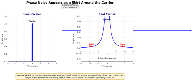
Phase noise is not simply "frequency inaccuracy," nor is it the spectrum analyzer’s noise floor. It describes the random phase fluctuations of an oscillating signal. A frequency source can have a very accurate long-term average frequency, yet its phase still jitters in the short term. Projected into the frequency domain, this jitter manifests as the noise skirt around the carrier.
01 Core Concepts of Phase Noise
· Phase noise describes the random jitter of the carrier phase, not a simple frequency error.
· The dBc/Hz specification on a datasheet must always be read together with the offset frequency. Never look at a single number in isolation.
· What engineers really care about is whether these phase fluctuations translate into adjacent-channel leakage, receiver noise floor degradation, EVM, radar clutter, or sampling clock jitter.
For example, a typical frequency source specification:
10 kHz offset Phase noise = -100 dBc/Hz
100 kHz offset Phase noise = -125 dBc/Hz
1 MHz offset Phase noise = -150 dBc/Hz
Here, 10 kHz, 100 kHz, and 1 MHz are not carrier frequencies—they are the offset frequencies from the carrier. Simply saying "phase noise −120 dBc/Hz" has virtually no engineering significance.
Think of the carrier as an ideal needle. A real oscillator’s phase noise grows a skirt around that needle. Phase noise very close to the carrier typically affects near-end blocking, radar close-range strong/weak target discrimination, and in-loop PLL noise. Phase noise farther from the carrier typically affects adjacent channels, wideband noise floor, integrated jitter, and high-speed sampling.
02 Understanding Phase Noise
An ideal sinusoidal signal can be written as:
v(t) = A × cos(2πf₀t)
In a real signal, the phase is not perfectly stable but carries a small time-varying perturbation:
v(t) = A × cos(2πf₀t + φ(t))
Here φ(t) is the random phase fluctuation. When it is small, the time-domain waveform may not look noticeably different, but in the frequency domain it creates a continuous noise spectrum on both sides of the carrier.
Phase noise is commonly expressed as the single-sideband phase noise L(f), in units of dBc/Hz.
dBc indicates the noise power relative to the carrier power, and Hz normalizes it to a 1 Hz bandwidth.
The relationship between phase noise and jitter:
RMS phase jitter ≈ √(2 × ∫ L(f) df)
RMS time jitter σₜ = RMS phase jitter σφ / (2πf₀)
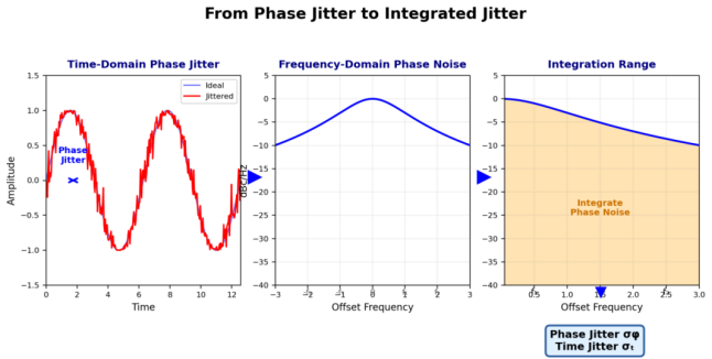
Note that L(f) must first be converted from dBc/Hz to linear units before integration—you cannot directly sum dB values. The integration range is not arbitrary; it must come from system requirements. A communication system may care about phase error within a certain demodulation bandwidth, while a high-speed sampling system may care about the impact of clock jitter on the input frequency.
03 Key Specifications in Engineering
Close-in Phase Noise
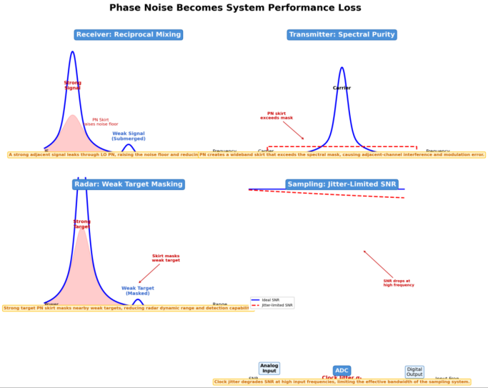
Close-in phase noise determines whether a weak signal can be observed near a strong one. When a receiver encounters a strong blocking signal, the local oscillator’s phase noise mixes with that strong signal, shifting its phase noise down to the IF or baseband—this is called reciprocal mixing. The weak signal may not be buried by the front-end thermal noise, but rather by the "phase noise floor brought in" by the strong signal.
Mid-to-Far Offset Phase Noise
Mid-to-far offset phase noise typically affects adjacent-channel leakage, spectral purity, and wideband system noise floor. For sampling clocks, phase noise is often converted into time jitter. The higher the input frequency, the greater the sampling amplitude error caused by the same clock jitter:
SNR_jitter ≈ −20 × log₁₀(2π × f_in × σₜ)
At low input frequencies, sampling clock jitter may not be the primary bottleneck; at high input frequencies, even if the ADC itself has excellent specifications, clock jitter can cap the achievable SNR.
Also distinguish spurs from phase noise. Phase noise produces a random noise skirt, while spurs appear as discrete spectral lines. Spurs may not be fully captured by "integrated phase noise," but they can still cause serious problems in communications and radar.
04 Phase Noise in Real Systems
■ Receiver: LO phase noise affects reciprocal mixing and demodulation quality. Even with a good noise figure, phase noise can raise the effective noise floor beyond what the thermal noise alone would suggest.
■ Transmitter: Frequency source phase noise affects transmit spectral purity, adjacent-channel power, and modulation error. Spectral problems after the PA are not always due to nonlinearity—they may originate from the upstream LO, PLL, reference source, or modulation clock.
■ Radar: Phase noise manifests as a noise skirt around strong targets. A very strong near-range reflection raises the surrounding noise floor, making nearby small targets harder to detect. FMCW radar also needs to consider chirp linearity, PLL modulation noise, and leakage paths.
■ High-Speed Sampling: Sampling clock phase noise ultimately becomes aperture jitter. The higher the input frequency and the target dynamic range, the more stringent the clock requirements become.
05 Common Misconceptions
1. Comparing only a single offset point — Device A may be better at 10 kHz and Device B better at 1 MHz. Which one fits depends on the system’s sensitive offset range.
1. Treating dBc/Hz as dBm — Carrier power, measurement bandwidth, and the spectrum analyzer’s noise floor all affect the actual reading and measurement uncertainty.
2. Conflating phase noise with spurs — Random skirts and discrete spectral lines have different origins, test methods, and system impacts.
3. Assuming a smaller or larger PLL loop bandwidth is always better — Loop bandwidth changes the weighting of reference noise, phase detector noise, divider noise, and VCO noise. Optimization must consider the reference source, VCO, lock time, modulation requirements, and spur risk.
4. Unclear test reference plane — Phase noise measurements are easily influenced by instrument noise floor, external reference quality, power supply noise, ground loops, cable shielding, and environmental vibration.
Three questions to ask before any phase noise test:
· Is the carrier power appropriate? Is the instrument noise floor low enough? Are the reference source, power supply, and shielding clean?
06 Engineering Evaluation and Selection
1. Clarify its role in the system — Receiver LO, transmit LO, PLL reference, sampling clock, radar chirp source, or external instrument reference? Different roles have different sensitive metrics.
5. Determine the offset frequency range of concern — A receiver cares about how far the strong interferer is from the desired signal; a transmitter cares about the spectral mask and adjacent-channel requirements; a sampling system cares about the input frequency and integrated jitter bandwidth.
6. Convert the phase noise curve into a system metric — Communications: EVM, adjacent-channel power, and reciprocal mixing. Sampling: σₜ and SNR ceiling. Radar: strong-target skirt and weak-target visibility.
7. Check spurs separately — Reference spurs, power-supply spurs, fractional-N spurs, and digital crosstalk must not be masked by a smooth phase noise curve.
8. Document test conditions — Carrier power, offset range, RBW, correlation mode, external reference, power supply, shielding, and temperature all must be recorded. Phase noise curves measured under different conditions cannot be directly compared.
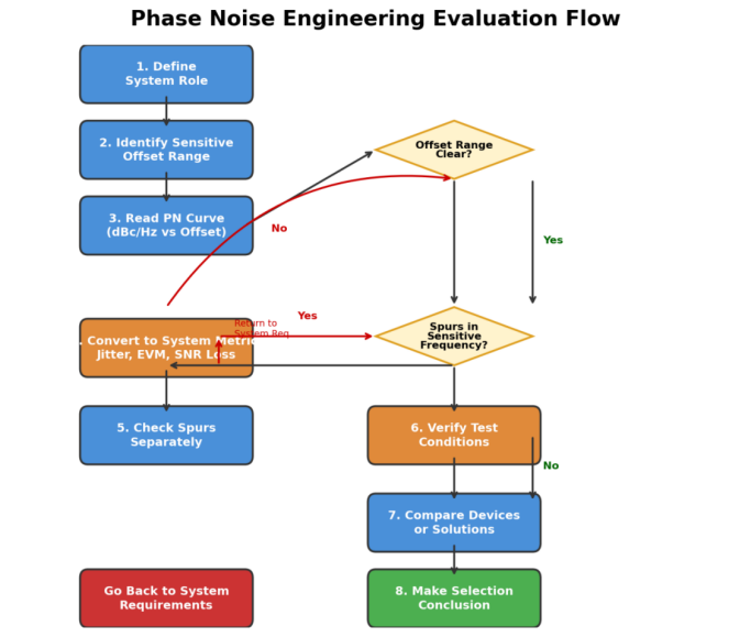
The selection process can be compressed into these rules:
· Start with the system role, then determine the sensitive offset range.
· Never look at a single-point phase noise value; examine the curve and integration range.
· Judge random phase noise and discrete spurs separately.
· For receivers, evaluate reciprocal mixing; for transmitters, evaluate spectral purity.
· For sampling systems, evaluate integrated jitter and the SNR ceiling.
· Every test conclusion must specify the reference plane, bandwidth, carrier power, and instrument noise floor.
07 Final Thoughts: Grounding Key Decisions in Engineering
Phase noise appears to be a frequency source specification, but in practice it cascades into receiver sensitivity, adjacent-channel rejection, EVM, spectral purity, radar weak-target detection, and high-speed sampling dynamic range.
It is not an isolated number but a curve that must be read within the context of the system. The key to evaluating phase noise is to consider offset frequency, noise density, integration range, spurs, and test conditions together.
As long as you can clearly answer: which offsets the system is sensitive to, through which path phase noise becomes a performance loss, and whether the test truly measures the device under test—phase noise will no longer be just a string of dBc/Hz numbers on a datasheet, but a computable, comparable, and diagnosable engineering metric.